Wednesday 6 December 2017

Assessing the gearbox

Photos by Rob Bishop
  
This is the story of the gearbox so far; it is like the rest of the project a mix of good and bad news.


45 years after it was taken out of use the interior of the gearbox is a beautiful thing, and once the bell cranks which operate the selector have been freed off, it performs beautifully.
How it works is very simple. It is a two speed box, with both speeds being available in forwards & reverse. The drive from the engine comes in on a bevel gear behind the forward/reverse selector. This meshes with one of the two bevel gears on the upper shaft. The upper shaft is splined, so depending on which direction is selected the upper shaft rotates either clockwise or anticlockwise. 
Also on the upper shaft are two chain wheels. The larger one on the left in the photo is for top gear, while the smaller wheel on the right is the low speed gear. Both wheels & chains are rotated by the upper shaft.
The lower chain wheels are mounted on roller bearings which rotate around the lower shaft. The central section of the shaft is splined, and drives a small external pinion which engages with the large gear wheel on the lay shaft. 
The drive from the high/low chain wheels to the splined shaft is via dog clutches, operated by the high/low selector.  


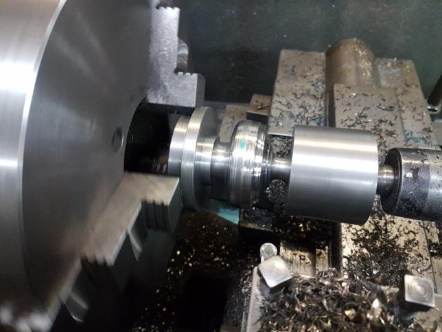
The photo below shows the high ratio gear, with the chain removed. The dog clutch is engaged and the chain wheel is driving the output shaft. The use of a dog clutch to change speed on the move is very crude and it accounts for a lot of the problems which exist and also places some of the historic stories into context. In a wonderful first-hand account published in FRM26 Bill Willans, who accompanied the loco on a lot of the trials states ‘On one occasion we broke some slates; she took a little care to start a train gently. On another occasion a drawbar was broken…’ 

It is easy to see why such things may occur. There are 2 ways to get a dog clutch to engage while the loco is moving; you can either be brutal or gentle. If you are brutal it may cause a snatch, if you are gentle the train can lose momentum, the couplings on a loose coupled train relax and when you let the clutch out, you can cause a snatch, particularly if the train has lost a lot of speed. It a nutshell it is never going to be good.


One of Bill Willans' other little snippets suggests that the brutal gear change was the order of the day. He recalls a failure when the loco was running on the FR, ‘the bell crank that operated the first gear fractured. The Glaslyn Foundry forged a replacement and a beautiful job they made of it’. To engage that gear, there must be a need to use quite a bit of force!


This is the bell crank for the high/ low gear selector. It is the component replaced by Glaslyn Foundry. Is this ‘the beautiful job’ or did it need replacing on a regular basis throughout its career?

The rather harsh gear change also accounts for the damage to the saddles which mount the gearbox on the lay shaft; when you engage gear, the forces on the pinion drive to the layshaft will place the saddles in tension. As these are part of a casting and cast iron does not behave well under tension, these forces have resulted in failure. The photo below shows the saddle in situ on the lay shaft, with the missing chunk being all too evident.


The gear box has been temporarily placed back in the frames to enable the team to measure up clearances and devise a solution. The previous repair option, brazing the saddle back on has been discounted, and we have reservations about a cast iron welding repair as the shock loadings which have caused the damage will reoccur once the loco is running again.
When we took the loco to pieces, the function of a couple of short little stays between the gearbox and the loco frames where not apparent. Their role became all too apparent in the trial run; these stays are an attempt to increase the degree of security between the gearbox and the frames. One of the stays can be seen on the gear box to the right side of the pinion.


Current thoughts on a repair are to form two large brackets which pick up from the annular row of bolts on the gear box end cover and to bolt these brackets to the frame stretchers.  

Saturday 24 June 2017

Flats and Knobs

Photos by Rob Bishop


Just as nature abhors a vacuum, so the Ffestiniog Railway abhors an empty waggon. With the frames on their wheels there was an urgent need to re-load the WD flat before someone else took a shine to it. This is waggon 72, the ‘in’ tray, with (from left to right) the gearbox, the 1945 MR4 engine and parts of the cab.


The next item on the agenda is the gearbox, another load for waggon 71.


Something that needs some thinking about are the two saddles which locate the gearbox on the lay shaft. The gearbox casing is a casting and both saddles have been damaged and repaired in the past. 


KS4415 has very clean lines. The gear box oil filler which projects through the running plate on the right hand side harks back to an earlier time.


 Its restoration is not on the critical path, but Rick couldn’t help himself!


Tuesday 20 June 2017

Frame assembly completed!

Progress photos by Rob Bishop


Trial fit of front dragbox 
(The front frame stretchers are offset; the coupling is in the middle of the buffer beam!)


Drawbeam assembly ready for the paint shop


The lay shaft is a huge lump of steel which runs across the full width of the loco at the front. It is static and the two prominent ‘bearings’ in the frames support the fixed shaft. The rotating component is the ‘sprocket sleeve’. This is the layshaft. The sprocket sleeve sits on the left hand (polished) end. The milled flat on the shaft feeds oil to the Sumet metal (bronze) bearings fitted inside the sprocket sleeve.


The sprocket sleeve


The sprocket sleeve itself


The splined sprocket sleeve carries the large gear wheel, driven by the gearbox, the drive chain sprocket & the transmission brake drum. While the drive chain sprocket is machined to fit the splines the gear wheel and transmission brake are secured by keys. To re-gauge the loco the position of the drive sprocket can be varied by inserting different spacers onto the sprocket sleeve.


When first built the frames on KS4415 were continuous on both sides. Making the front section of the frames removable makes a lot of sense when it comes to installing the sprocket sleeve onto the layshaft. Dave High ponders how to make the sling slide through the footplating. Was the frame modification made in 1929 to facilitate re-gauging to 3’ for use at Castlederg?


The spectacular Thrackway washer which secures the layshaft to the end bearings.


The sprocket spindle before & after. 
(Gearbox still to restore. Transmission brake pads to re-fit)


All wheels turned


Chains delivered


Felt seals manufactured for axleboxes


Axleboxes assembled & fitted to the radius rods. 
(The hind wheelset is on the left, this has only one chain sprocket 
which is on the other side, out of camera shot)


A chance for the wheelsets to shine and re-create two images from "15/- change".  
(Unlike the "15/- change" images, the sub frames have already been attached to the main frames. 
The hollow box section in the spring clamps was a temporary measure to hold the axleboxes level while the chain tension was being adjusted)


With the springs fitted and the box section removed the wheelsets do their own thing 
as Matty Wolstenholme & Ed Ford propel them towards the frames.


Having briefly shone, the wheelsets become accustomed to life in the shade.


The clevis which attaches the rear radius rod to the frame. 
(This section of frame replaced as part of the restoration)


Dragbox installation


Big nuts. 

Although the project  uses imperial fastenings, 
the modern dragbox has been assembled with metric set screws.


Chopper coupling fitted


The ‘split face’ chopper couplings are recovered old units, similar in appearance those fitted in early 1929. Ultimately the loco will be fitted with side chains too.


Brake gear erected; the brake blocks have subsequently been fitted.


The completed frame assembly.
 The handbrake stanchion bolts to the cast iron cab floor, 
which is supported by two further upright castings


Wednesday 24 May 2017

Component preparation

Photos by Rob Bishop & Emily High


Three views capturing some of the bits that have recently been grit blasted, which provide a flavour for activities later this year.


The big bits in the foreground of this image  include the (from right to left), the covers for the cam shaft/ valve push rods and the gear train from the MDB4 engine (see photo below), followed by the cover for the gear wheel on the lay shaft, which forms part of the final drive and the casting which carries the starting mechanism (see 8th March 2017 update)


This is the final drive from the gear box to the lay shaft, which is protected by the cover in the centre of the first image. The ‘shadow’ of the cover can be seen. The upper strap of the transmission brake is also visible in this view.


The large wheel on the left of the view  is the drum for the transmission brake. Other transmission brake components on view include the two crescent shaped plates (centre) and the brake shoes (rear), see 8th March 2017 update for the relationship of the transmission brake bits. The other components visible include the drive pulley for the water pump/ fan belt, a cab stanchion, parts from the lay shaft and the engine starting mechanism.


An easy one to spot. The cab rear sheet, complete with drivers’ seat.


Sunday 21 May 2017

Turning the wheels

Photos by Rob Bishop

A short and sweet report.

The picture of Rhys Hughes below says it all - the wheels for KS4415 are being turned and the journals skimmed...